EC > GATE 2015 SET-2 > Analog Circuits
In the circuit shown, V0 = V0A for switch SW in position A and V0 = V0B for SW in position B. Assume that the opamp is ideal. The value of V0B⁄V0A is __________.
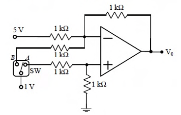
Correct : 1.5
Similar Questions
Consider a four bit D to A converter. The analog value corresponding to digital signals 0000 and 0001 are 0 V and 0.0625 V respectively. The analog value (in Vo...
The circuit shown in the figure has an ideal op-amp. The oscillation frequency and the condition to sustain the oscillations, respectively, are
If the circuit shown has to function as a clamping circuit, then which one of the following conditions should be satisfied for the sinusoidal signal of period T...

Total Unique Visitors
Loading......