EC > GATE 2014 SET-3 > Combinational Circuits
In the circuit shown, W and Y are MSBs of the control inputs. The output F is given by
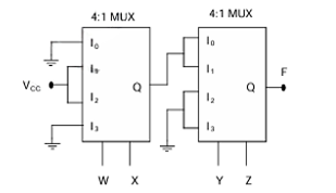
Correct : c
Similar Questions
A full adder and an XOR gate are used to design a digital circuit with inputs X, Y, and Z, and output F, as shown below. The input Z is connected to the carry-i...
Consider the 2-bit multiplexer (MUX) shown in the figure. For OUTPUT to be the XOR of C and D, the values for A0, A1, A2, and A3 are ____________.
In the circuit shown, A and B are the inputs and F is the output. What is the functionality of the circuit?

Total Unique Visitors
Loading......