EC > GATE 2014 SET-1 > Combinational Logic
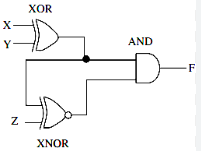
The output F in the digital logic circuit shown in the figure is
Correct : a
Similar Questions
The figure below shows a multiplexer where S₁ and S₀ are the select lines, I₀ to I₃ are the input data lines, EN is the enable line, and F(P,Q,R) is the output....
In a half-subtractor circuit with X and Y as inputs, the Borrow (M) and Difference (N = X - Y) are given by
Mr. X speaks _________ Japanese _________ Chinese.

Total Unique Visitors
Loading......