Computer Sciences > GATE 2023 > Digital Logic
A Boolean digital circuit is composed using two 4-input multiplexers (M1 and M2) and one 2-input multiplexer (M3) as shown in the figure. X0-X7 are the inputs of the multiplexers M1 and M2 and could be connected to either 0 or 1. The select lines of the multiplexers are connected to Boolean variables A, B and C as shown.
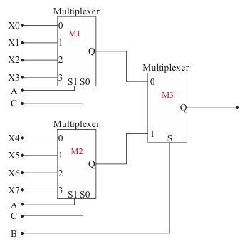 Which one of the following set of values of (X0, X1, X2, X3, X4, X5, X6, X7), will realise the Boolean function A̅+A̅C̅+A⋅B̅⋅C?
Correct : a
Similar Questions
Consider the minterm list form of a Boolean function F given below.
F(P, Q, R, S) = Σm(0, 2, 5, 7, 9, 11) + d(3, 8, 10, 12, 14)
Here, m denotes a minterm...
A multiplexer is placed between a group of 32 registers and an accumulator to regulate data movement such that at any given point in time the content of only on...
Consider a system that uses 5 bitsfor representing signed integers in 2’s complement
format. In this system, two integers 𝐴 and 𝐵 are represented as 𝐴=01010 an...

Total Unique Visitors
Loading......