Civil Engineering > GATE 2020 SET-2 > Structural Analysis
Joints I, J, K, L, Q and M of the frame shown in the figure (not drawn to the scale) are pins. Continuous members IQ and LJ are connected through a pin at N. Continuous members JM and KQ are connected through a pin at P. The frame has hinge supports at joints R and S. The loads acting at joints I, J and K are along the negative Y direction and the loads acting at joints L and M are along the positive X direction.
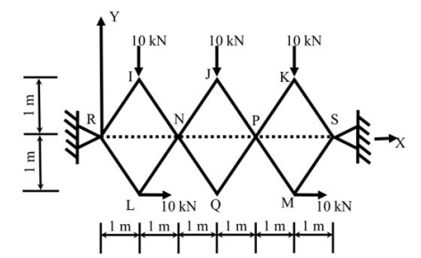 The magnitude of the horizontal component of reaction (in kN) at S, is
Correct : c
Similar Questions
The figure shows a two-hinged parabolic arch of span L subjected to a uniformly distributed load of intensity q per unit length.
The maximum bending moment...
A planar truss tower structure is shown in the figure.
Consider the following statements about the external and internal determinacies of the truss.
(P) E...
The value of M in the beam ABC shown in the figure is such that the joint B does not rotate.
The value of support reaction (in kN) at B should be equal to _...

Total Unique Visitors
Loading......