Biomedical Engineering > GATE 2022 > Digital Circuits
Input bits X and Y are added by using the combinational logic as shown below. S represents the sum of the two bits. For a correct implementation of the sum, the signals D0, D1, D2, D3 are _______, _______, _______, and _______, respectively.
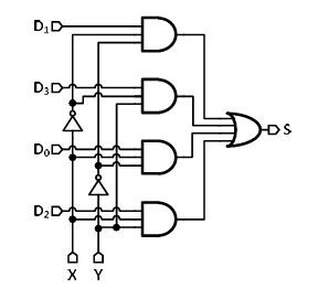
Correct : a
Similar Questions
The circuit shown in the figure functions as which one of the following digital circuit blocks?
In the circuit diagram shown below, the logic gates operate with a supply voltage of 1 V. NAND and XNOR have 200 ps and 400 ps input-to-output delay, respective...
You should _________ when to say _________.

Total Unique Visitors
Loading......